It generates a setting based on the closed wire in the left section of
the setting which exists on the Y-Z plane.
TOOL
When starting this command, the command which was starting before it is
automatically ended and the generated setting becomes a chosen condition
(red display).
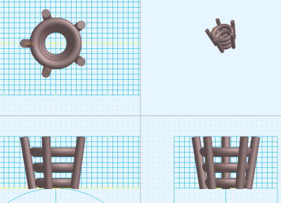
A procedure is shown below.1. It generates a closed wire in the left section
of the setting.
It starts [Wire] command and it generates a closed wire in the left section of the setting in the Y-Z plane.
2. When inputting the size of the setting in the numerical value
It starts [Numeric Mode] command and it makes a numerical value input
state.
The starting of [Numeric Mode] command can be omitted when starting a menu
while pushing Numeric Mode Shortcut Key(Generally :Shift ), too.
3. When displaying the size of the setting in the numerical value
It starts [Show The Number] command and it makes a numerical value display
condition.
4. It starts [Generate Setting] command.
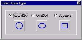
5. The DIALOG which chooses a setting shape is displayed. Click a button with the mouse or push a Short-cut Key.
[Select Gem Type]Dialog Box
The display of the DIALOG can be omitted when starting a menu while pushing
a corresponding Short-cut Key.
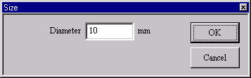
6. In case of the numerical value input state
[Size] Dialog Box
The [Size] Dialog Box is displayed. It specifies the size of the setting.
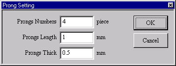
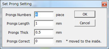
7. When the setting shape is a round frame (The oval/square frame doesn’t have a prongs.)
[Prong Setting] Dialog BoxThe [Prong Setting] Dialog Box is displayed.
It specifies the number, the length and the thickness of the prong. The
length is the distance of the part which overhung from the setting top.
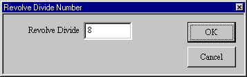
8. The [Revolve Divide Number] Dialog Box is displayed. It specifies a Revolve Divide Number.
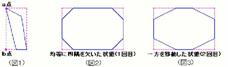
9. In case of the mouse input state (except the numerical value input state)
(a) It generates a setting to the screen half size and TRACKER is displayed on the XY plane.
TRACKER color
Blue : For the size change.
Dark Green : For the square four corner lack. (Only the square frame)
(b) It drags TRACKER(Blue) for the size change and it changes a size.
Drag - It is not in the movement limitation.
Mouse Limit Key (Generally :Ctrl ) + Drag - It limits a movement to the
vertical/horizontal/slant (45 degrees)
direction.
When limiting input, continue to push Mouse Limit Key until the drag ends. At this time, in case of the numerical
value display condition, it displays movement distance at the numerical value
10. In case of the square frame (Regardless of the mouse input/the numerical value input)
It drags TRACKER (Dark Green) for the four corner lack and it is possible to lack the four corners. It is possible to
return to the condition before lacking the four corners when starting [Delete]
command.。 [Revolve Divide Number] Dialog Box
This command doesn’t end automatically. As for the way of ending, refer
to The way of command’s ending. As for the
TRACKER, refer to The way of the TRACKER operation. In [Environment] command,
Numeric Mode Short-cut Key and Mouse Limit Key can be changed, too. The
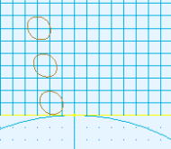
prong can be put onto the straight line which linked the Control point
which is the nearest the A point and the Control point which is the nearest
the B point of Figure 1. In case of the square frame, there is TRACKER
for the four corner lack inside TRACKER for the size change. The four corners
lack when dragging TRACKER for the four corner lack. As for the 1st, both
sides lack. Since the 2nd, it moves to the specified direction.
Since Ver1.1
It corresponds to two or more sections up to five sections
In the Prong setting of the round, the fingernail can be corrected in the
frame according to the correction value.