It generates a Wire.
| TOOL |
 |
Function Key
|
| no-function Key |
Usually,Object |
| F5 key is pushed and it is command starting. |
Limit |
| F6 key is pushed and it is command starting. |
Rotate SymmetryWire |
| F7 key is pushed and it is command starting. |
1 axis SymmetryWire |
| F8 key is pushed and it is command starting. |
2 axis SymmetryWire |
| F9 key is pushed and it is command starting. |
Passage Point |
| F10 key is pushed and it is command starting. |
Spiral |
When starting this command, the command which was starting before it is automatically ended and the generated Wire
becomes a chosen condition (red display).
A procedure is shown below. (It does any one of three planes (X-Y, Y-Z, Z-X).)
1. When inputting the direction (angle) of the Control point segment and R in the numerical value
F5 key is pushed, and the [Limit] mode is taken.
2. When [Wire]command is done with [Rotate Symmetry].
F6 key is pushed, and the [Rotate Symmetry] mode is taken.
3. When [Wire]command is done with [1 axis Symmetry].
F7 key is pushed, and the [1 axis Symmetry] mode is taken.
4. When [Wire]command is done with [2 axis Symmetry].
F8 key is pushed, and the [2 axis Symmetry] mode is taken.
5. When [Wire]command is done with [Passage Point].
F9 key is pushed, and the [Passage Point] mode is taken.
6. When [Wire]command is done with [Spiral].
F10 F10 key is pushed, and the [Spiral] mode is taken.
Rotate Symmetry, 1 axis Symmetry, 2 axis Symmetry, and Spiral cannot be started simultaneously.
7. When displaying displacement quantity with the Control point position which was specified immediately before in the
numerical value It starts P23 [Show The Number] command and it makes a numerical value display condition.
8. When the numerical input of the amount of variation with The specified Control point position is carried out
It starts [Numeric Mode] command and it makes a numerical value input state.
The starting of [Numeric Mode] command can be omitted when starting a menu while pushing Numeric Mode Shortcut
Key(Generally : Shift ), too.
9. It starts [Wire] command.
10. In case of [Spiral] mode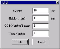
[Spiral]Dialog
The [Spiral] Dialog Box is display. The following information is set up. A push on the O.K. button generates a spiral.
(a) Diameter
The Diameter of Spiral(mm)
(b) Height(1 turn)
The Height(1 turn) of Spiral(mm)
(c) Ctl-P Number(1 turn)
The Control Point(1 turn) of Spiral
(d) Turn Number
The Turn Number of Spiral
11. The DIALOG which specifies Open/Close of the Wire is displayed. Click
a button with the mouse or push a Short-cut Key.
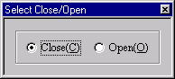
[Select Close/Open]Dialog Box
The display of the DIALOG can be omitted when starting a menu while pushing a corresponding Short-cut Key. In case
of Open, it doesn’t connect a start point and a terminus and in case of Close, it connects a start point and a terminus.
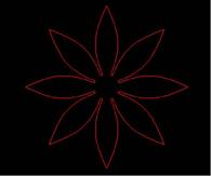
12. In case of [Rotate Symmetry] mode
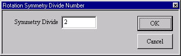
[[Rotate Symmetry Divide Number]Dialog Box
(a) The [Rotate Symmetry Divide Number] Dialog Box is displayed. The
Divide Number of Rotate Symmetry is
specified.(A default is 2 and a maximum of 50. 5 and 11 are invalid.)
(b) Arbitrary one plane of three planes is chosen. An axis (green) is displayed on the selected plane.
(c) A Wire is drawn on the fan-like range.
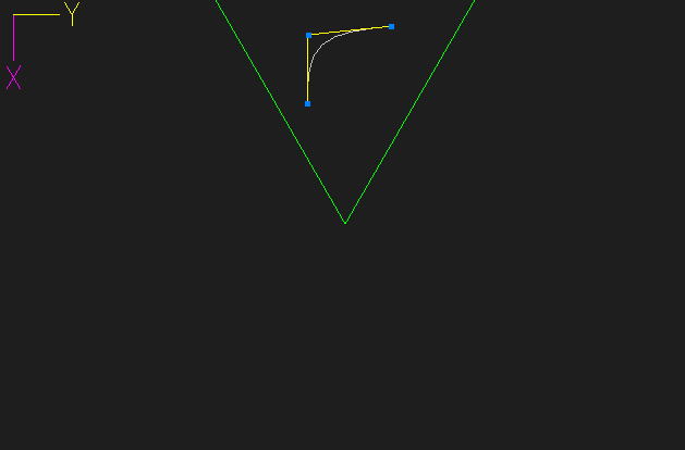
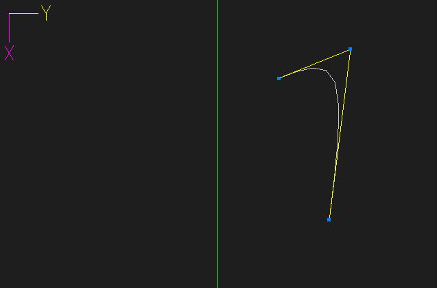
13. In case of [1 axis Symmetry] mode
(a) Arbitrary one plane of three planes is chosen. An axis (green) is displayed on the selected plane.
(b) A curve is drawn in the range center axis right and left.
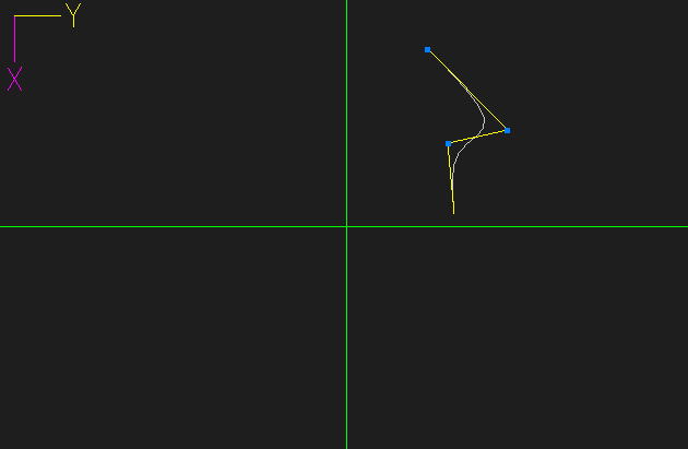
14. In case of [2 axis Symmetry] mode
(a) Arbitrary one plane of three planes is chosen. An axis (green) is displayed on the selected plane.
(b) A Wire is drawn in either of four ranges.
15. In case of the numerical value input state
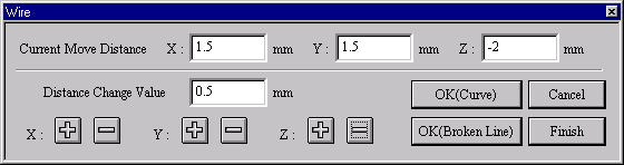
[Wire]Dialog Box
(a) The left button of a mouse is clicked in the position of the starting point.
(b) The [Wire] Dialog Box is displayed. It specifies movement distance, The point determines Curve or Broken Line.
(c) The above is repeated and an end button is clicked. It makes the number of the effective Control points 3-50. (In
case of Close, Control points 2-50)
16. In case of the mouse input state (except the numerical value input state)
(a) It clicks the left button of the mouse in the position with the Control point of the Wire and it specifies a Control
point.
Left button click - The Control point of the curve point.
Broken Line Key (Generally :Shift ) + Left button click - The Control point
of the broken line point.
(b) It moves a mouse cursor to the position with the following Control point. At this time, it is connected with the
mouse cursor and a curve is displayed.
It moves cursor - It is not in the movement limitation.
Mouse Limit Key (Generally :Ctrl ) + It moves cursor - It limits a movement
to the vertical/horizontal/slant (45
degrees) direction.
When limiting a movement, continue to push Mouse Limit Key until it specifies a Control point.
(c) It repeats above-mentioned a. b. It makes the number of the effective Control points 3-50.
In case of the numerical value input state, the [Wire Information] Dialog Box is displayed.
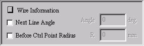
When checking ”Next Line Angle” the angle of the specification Control point segment can be specified this time
to the Control point segment which has been specified immediately before. The right direction becomes a positive
and the left direction becomes a negative angle. When checking ”Before Ctrl Point Radius” It is possible to do the
R specification of the Control point part which has been specified immediately before. There is a case of processing
being impossible depending on the segment distance of the place around the object Control point and specification
R because it adds a Control point automatically and it processes. In case of the numerical value display condition,
it displays the displacement quantity of the previous Control point position and the mouse cursor location. It is
possible to do an input Control point immediately ahead invalid when starting P17 [Delete] command.
17. In case of Open and the specified control point is two points.
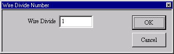
[Wire Divide Number]Dialog Box
The dialog which specifies an insertion control point is displayed. The
number of control points inserted in two points is specified.
18. In case of each Symmetry Mode
(a) Rotate Symmetry carries out the number shear rotation copy of Rotate Symmetrical Division after curvilinear
generation, and, in Open, each curve is connected. In Open, it rotates from a point near from an axis (green), and
the last one point is not connected.
When Rotate Symmetry, the way which does not specify a control point on an axis is made safely. It makes the
number of the effective Control points 1-50/Rotate Symmetrical Division Number.
(b) 1 axis symmetry carries out a Mirror Copy after curvilinear generation, and, in Open, a curve is connected.
Connecting a near distance from an axis (green) in Open, the last does not connect. When the distance from an
axis is the same, a curved terminal point is connected. It makes the number of the effective Control points 2-25.
(c) 2 axis symmetry carries out a Mirror Copy after curvilinear generation, and, in Open, a curve is connected.
Connecting a near distance from an axis (green) in Open, the last does not connect. When the distance from an
axis is the same, a curved terminal point is connected. However, when the center of a cross axis is made into a
control point, the terminal point of the curve serves as connection with the nearest axis. It makes the number of
the effective Control points 2-25.
19. It starts [Wire Deform] command.
In the case of each Symmetry mode, if [Wire Deform] of the range which generatedWire is possible and [Wire Deform]
of the range is performed, other symmetrical portions will interlock and change to it.
This command doesn’t end automatically. As for the way of ending, refer
to The way of command’s ending. As for the
TRACKER, refer to The way of the TRACKER operation. In [Environment] command,
Numeric Mode Short-cut
Key, Line Mode Broken Line Key and Mouse Limit Key can be changed, too.
Refer to [Control Point and Passage Point] about Passage Point.

|
| |
| Copyright 2009 GLB Co., Ltd All Right Reserved |
|