|
|
2.7.3[Wire Deform] command
|
|
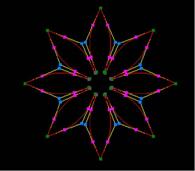
It moves, it inserts and it deletes a Control point with chosen object
(Wire).
NEW**It is possible to separate when right-clicking in the inserted point(
Pink).
| TOOL |
 |
Function Key
|
| no-function Key |
Usually,Wire Deform |
| F6 key is pushed and it is command starting. |
Rotate Symmetry Wire Deform |
| F7 key is pushed and it is command starting. |
1 axis SymmetryWire Deform |
| F8 key is pushed and it is command starting. |
2 axis SymmetryWire Deform |
| F9 key is pushed and it is command starting. |
Passage Point Wire Deform |
When starting this command, the command which was starting before it is automatically ended.
A procedure is shown below.
1. It chooses the object (Wire). (For the details, refer to P8 The way of choosing object.)
2. When [Wire Deform]command is done with [Rotate Symmetry].
F6 key is pushed, and the [Rotate Symmetry] mode is taken.
3. When [Wire Deform]command is done with [1 axis Symmetry].
F7 key is pushed, and the [1 axis Symmetry] mode is taken.
4. When [Wire Deform]command is done with [2 axis Symmetry].
F8 key is pushed, and the [2 axis Symmetry] mode is taken.
5. When [Wire Deform]command is done with [Passage Point].
F9 key is pushed, and the [Passage Point] mode is taken.
6. When displaying displacement quantity with the Control point position which was specified immediately before in the
numerical value It starts [Show The Number] command and it makes a numerical
value display condition.
7. When the numerical input of the amount of variation with The specified Control point position is carried out
It starts [Numeric Mode] command and it makes a numerical value input state.
The starting of [Numeric Mode] command can be omitted when starting a menu while pushing Numeric Mode Shortcut
Key(Generally : Shift ), too.
8. It starts [[Wire Deform] command.
9. In case of [Rotate Symmetry] mode
(a) The [Rotate Symmetry Divide Number] Dialog Box is displayed. The Divide
Number of Rotate Symmetry is specified.(A default is 2 and a maximum of
50. 5 and 11 are invalid.)
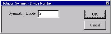
[Rotate Symmetry Divide Number]Dialog Box
(b) Arbitrary one plane of three planes is chosen. An axis (green) is displayed on the selected plane.
10. In case of [1 axis Symmetry] mode
Arbitrary one plane of three planes is chosen. An axis (green) is displayed on the selected plane.
11. In case of [2 axis Symmetry] mode
Arbitrary one plane of three planes is chosen. An axis (green) is displayed on the selected plane.
12. In case of the numerical value input state
(a) The TRACKER is displayed in the Control point position.
TRACKER color is Blue : The Control point of the curve point, Dark Green : The Control point of the broken
line point, Pale Purple : The halfway point (The addition insertion position).
(b) It clicks the left button according to TRACKER in the mouse cursor.
i. In case of the curve point/the broken line point of Control point
Left button click - The choice of the Control point.
Left button drag - The choice of the Control point.
With the above key + Ctrl Point Add Key (Generally : Ctrl ), it is chosen
in the addition by the selection
control point before it.
Line Mode Change Key (Generally : Shift ) + Left button click - The reverse
of the curve point/the broken
line point and the choice of the Control point.
ii. In case of the halfway point
Left button click - The choice of the Control point.
Left button drag - The choice of the Control point.
With the above key + Ctrl Point Add Key (Generally : Ctrl ), it is chosen
in the addition by the selection
control point before it.
Line Mode Change Key (Generally :Shift ) + Left button click - The reverse
of the curve point/the broken
line point and the choice of the Control point.
The TRACKER color is Yellow : The choice Control point (The movement and deletion point).
(c) The [Wire Deform] Dialog Box is displayed. It specifies movement distance.
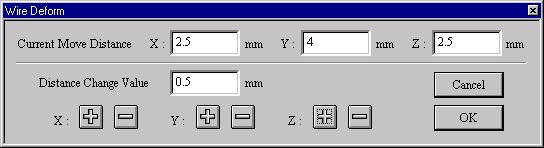
[Wire Deform]Dialog Box
13. In case of the mouse input state (except the numerical value input state)
(a) The TRACKER is displayed in the Control point position.
TRACKER color is Blue : The Control point of the curve point, Dark Green : The Control point of the broken
line point, Pale Purple : The halfway point (The addition insertion position).
(b) It clicks the left button according to TRACKER in the mouse cursor.
i. In case of the curve point/the broken line point of Control point
Left button click - The choice of the Control point.
Left button drag - The choice of the Control point.
With the above key + Ctrl Point Add Key (Generally : Ctrl ), it is chosen
in the addition by the selection
control point before it.
Line Mode Change Key (Generally : Shift ) + Left button click - The reverse
of the curve point/the broken
line point and the choice of the Control point.
ii. In case of the halfway point
Left button click - The choice of the Control point.
Left button drag - The choice of the Control point.
With the above key + Ctrl Point Add Key (Generally :Ctrl ), it is chosen
in the addition by the selection
control point before it.
Line Mode Change Key (Generally : Shift ) + Left button click - The reverse
of the curve point/the broken
line point and the choice of the Control point.
The TRACKER color is Yellow : The choice Control point (The movement and deletion point).
(c) It drags chosen TRACKER (yellow).
Drag - It is not in the movement limitation.
Mouse Limit Key (Generally : Ctrl) + Drag - It limits a movement to the
vertical/horizontal/slant (45 degrees) direction.
When limiting a movement, continue to push Mouse Limit Key until it specifies
a Control point. In case of thenumerical value display condition, it displays
the displacement quantity of the movement origin Control point position
and the mouse cursor location. The choice Control point can be deleted
when starting [Delete] command.
This command doesn’t end automatically. As for the way of ending, refer
to The way of command’s ending. As for the TRACKER, refer to The way of
the TRACKER operation. In [Environment] command, Line Mode Broken Line/Change
Key, Mouse Limit Key and Ctrl Point Add Key can be changed, too. When a
thing except 0 is set to the Tension Coefficient, it has an influence on
the thing except the moving Control point, too. For the details, refer
to [Tension Coefficient] command. Refer to [Control Point and Passage
Point] about Passage Point.
|