|
|
2.9.10[Base Wire Deform[Ctl-P]] command
|
|
This is Nothing in BASIC version.
It moves to the curvilinear position which specified the control point
of the solid (surface) chosen.
TOOL
|
 |
Function Key
|
| no-function Key |
Usually,Point Move |
| F5 key is pushed and it is command starting. |
Shape |
| F6 key is pushed and it is command starting. |
Shading |
| F7 key is pushed and it is command starting. |
1 axis symmetry |
| F8 key is pushed and it is command starting. |
2 axis symmetry |
| F9 key is pushed and it is command starting. |
Passage Point |
| F12 |
LIMIT |
When starting this command, the command which was starting before it is automatically ended.
A procedure is shown below.
1. It chooses the object (Wire) used as the standard. (For the details,
refer to The way of choosing object.)
2. When X coordinates are united
F5 key is pushed, and the [X Coordinates Deform] mode is taken.
3. When Y coordinates are united
F6 key is pushed, and the [Y Coordinates Deform] mode is taken.
4. When Z coordinates are united
F7 key is pushed, and the [Z Coordinates Deform] mode is taken.
5. When the object used as the standard after movement is not deleted
F8 key is pushed, and the [Base Wire Delete Off] mode is taken.
6. It starts [Base Wire Deform[Ctl-P]] command. (Display of the dark gray)
7. The object used as the candidate for edit is chosen. More than one can be chosen.
8. It starts [Base Wire Deform[Ctl-P]] command.
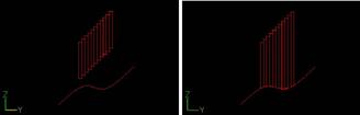
9. The TRACKER is displayed in the Control point position.
TRACKER color : Dark Green. : The section directional Control point line.
10. It clicks the left button according to TRACKER in the mouse cursor.
Left button click - The choice of the Control point.
Left button drag - The choice of the Control point.
With the above key + Ctrl Point Add Key (Generally : Ctrl ), it is chosen
in the addition by the selection control point before it.
TRACKER color : Yellow : The choice Control point (The movement point).
11. If the right button of a mouse is clicked, the specified control point is in agreement with a base line.
This command doesn’t end automatically. As for the way of ending, refer
to The way of command’s ending. As for the TRACKER, refer to The way of
the TRACKER operation.
Since Ver1.1
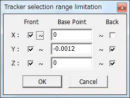
The range limitation function was made.
The control point is made non-display by acquiring the center of the object
automatically now and specifying the direction of side in the front side
back of the direction seen from each axis.
This item of effective comes to display it by putting the check.
Moreover, the back and Front
Front : small direction
Back: Maximum direction
When setting it as follows. The control point on X preaxial side (Because
it is the maximum value) becomes non-display.
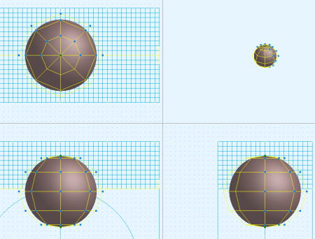
In the control point movement, when the range is exceeded, it becomes non-display.
(necesary more development. ) |