|
|
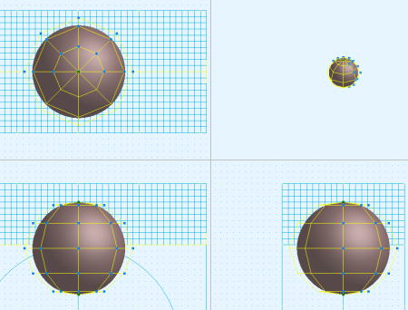
2.9.9 [Move Rails[Ctl-P]] command
|
|
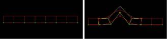
It moves the base line of the chosen object(curved surface).
| TOOL |
 |
Function Key
|
| no-function Key |
Usually,Move Rail |
| F5 key is pushed and it is command starting. |
Shape |
| F6 key is pushed and it is command starting. |
Shading |
| F7 key is pushed and it is command starting. |
1 axis symmetry |
| F8 key is pushed and it is command starting. |
2 axis symmetry |
| F9 key is pushed and it is command starting. |
Passage Point |
| F12 |
LIMIT |
When starting this command, the command which was starting before it is automatically ended.
A procedure is shown below.
1. It chooses the object (curved surface). (For the details, refer to The
way of choosing object.)
2. When the numerical input of the amount of variation with The specified Control point position is carried out
It starts [Numeric Mode] command and it makes a numerical value input state.
The starting of [Numeric Mode] command can be omitted when starting a menu
while pushing Numeric Mode Shortcut Key(Generally : Shift ), too.
3. When displaying movement distance with the Control point position in the numerical value before movement
It starts P23 [Show The Number] command and it makes a numerical value display condition.
4. When Shape is reversed from the present setup.
F5 key is pushed, and the [Shape] mode is taken. When effective, it can edit in the form at the time of generation.
5. When Shading is reversed from the present setup.
F6 key is pushed, and the [Shading] mode is taken. Shading will be carried
out by the solid of a perspective when effective.
6. When [Move Rails]command is done with [1 axis Symmetry].
F7 key is pushed, and the [1 axis Symmetry] mode is taken.
7. When [Move Rails]command is done with [2 axis Symmetry]
F8 key is pushed, and the [2 axis Symmetry] mode is taken.
8. When [Move Rails]command is done with [Passage Point]
F9 key is pushed, and the [Passage Point] mode is taken.
9. It starts [Move Rails[Ctl-P]] command.
10. In case of [1 axis Symmetry] mode
Arbitrary one plane of three planes is chosen. An axis (green) is displayed on the selected plane.
11. In case of [2 axis Symmetry] mode
Arbitrary one plane of three planes is chosen. An axis (green) is displayed on the selected plane.
12. In case of the numerical value input state
(a) The TRACKER is displayed in the Control point line position.
TRACKER color : Dark Green. : The section directional Control point line.
(b) It clicks the left button according to TRACKER in the mouse cursor.
Left button click - The choice of the Control point line.
Left button drag - The choice of the Control point line.
Line Mode Change Key (Generally : Shift ) + Left button click - The reverse
of the curve point/broken line point
and the choice of the Control point line
TRACKER color : Yellow : The choice Control point line (The movement point).
(c) It drags chosen TRACKER (Yellow).
(d) The [Move Rails[Ctl-P]] Dialog Box is displayed. It specifies movement
distance.
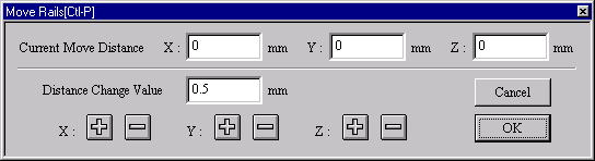
[Move Rails[Ctl-P]]Dialog Box
13. In case of the mouse input state (except the numerical value input state)
(a) The TRACKER is displayed in the Control point line position.
TRACKER color : Dark Green. : The section directional Control point line.
(b) It clicks the left button according to TRACKER in the mouse cursor.
Left button click - The choice of the Control point line.
Left button drag - The choice of the Control point line.
Line Mode Change Key (Generally : Shift ) + Left button click - The reverse
of the curve point/broken line point
and the choice of the Control point line
TRACKER color : Yellow : The choice Control point line (The movement point).
(c) It drags chosen TRACKER (Yellow). Drag - It is not in the movement limitation.
Mouse Limit Key (Generally : Ctrl ) + Drag - It limits a movement to the
vertical/horizontal/slant (45 degrees)
direction.
When limiting a movement, continue to push Mouse Limit Key until it specifies a Control point. In case of the
numerical value display condition, it displays the displacement quantity of the movement origin Control point
position and the mouse cursor location.
This command doesn’t end automatically. As for the way of ending, refer
to The way of command’s ending. As for the TRACKER, refer to The way of
the TRACKER operation. In P91 [Environment] command, Line Mode Broken Line/Change
Key, Mouse Limit Key can be changed, too. When a thing except 0 is set
to the Tension Coefficient, it has an influence on the thing except the
moving Control point, too. For the details, refer to [Tension Coefficient]
command. Refer to [Control Point and Passage Point] about Passage Point.
Since Ver1.1
The range limitation function was made.
The control point is made non-display by acquiring the center of the object
automatically now and specifying the direction of side in the front side
back of the direction seen from each axis.
This item of effective comes to display it by putting the check.
Moreover, the back and Front
Front : small direction
Back: Maximum direction
When setting it as follows. The control point on X preaxial side (Because
it is the maximum value) becomes non-display.
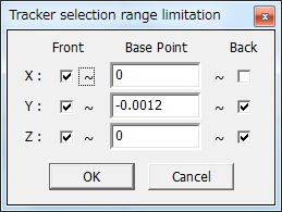
In the control point movement, when the range is exceeded, it becomes non-display.
(necesary more development. )
|